Koehler Automatic Dielectric Breakdown Tester

Koehler Automatic Dielectric Breakdown Tester provides reliable insulating oil testing with automated analysis and reporting.

Product Overview

The most important requirement of an insulating oil is a high dielectric strength. Determination of the dielectric breakdown voltage of insulating oils provides an early detection method for any reduction in the insulating properties and this can be monitored by using the Koehler Dielectric Breakdown Tester.

Features & Benefits

Voltage slew rate: 

  • K16185: 0 - 75kV ± 1kV
  • K16186: 0 - 90kV ± 1kV
    K16187: 0 - 105kV ± 1kV

Resolution (displayed): 0.1kV

Operating temperature: 0 – 50°C


Storage Temperature: -20°C to + 60°C

Temperature measurement resolution: ±1°C

Power frequency: 48 – 63Hz

High voltage shutoff time after breakdown, μs: < 10 (4 typical)

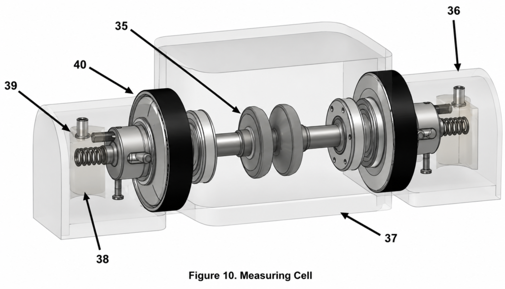
Measuring cell volume, cm3: 500

Koehler Automatic Dielectric Breakdown Tester

Insulating oils are used in the majority of high-voltage transformers, cables, switchgears, transducers, capacitors, and rectifiers and their purpose is for insulating electrically live parts and to carry off thermal energy. It’s essential that the quality of the insulating oil is checked at regular intervals to ensure a long equipment service life.

The most important requirement of an insulating oil is a high dielectric strength and this can be determined using the Koehler Dielectric Breakdown Tester which provides an early detection method for any reduction in the insulating properties.

• Conforms to ASTM D877, D1816, IEC 60156 and related test specifications

• Output voltage: K16185: 75kV, K16186: 90kV, K16187: 105kV

• Internal battery, external 12V power supply

• Measurement of silicone-based oils

• Internal temperature measurement of oil sample

• Automatic Vernier function for electrode gap spacing

• Built-in printer offers direct evaluation and reporting of results

• USB flash drive compatibility

About the Koehler Automatic Dielectric Breakdown Tester

During a test, alternating current (AC 50-60Hz) is supplied from the secondary winding contacts through the cell electrodes to the liquid sample in the cell. The breakdown occurs between the cell electrodes over the space filled by the liquid dielectric.

The Dielectric Tester contains a High Voltage Transformer. A microcontroller managing the invertor controls the voltage increase. The unit control board commands the controlled inverter.

29. High Voltage Contacts of the Output                   Electrodes

30. Oil Stirring Drive

31. Attachment Plate

32. Primary Winding

33. Secondary Winding Coi

34 .Magnetic Core

35. Measuring Cell (with the cover removed)

36. Measuring Cell High Voltage Electrodes

37.  Electrode Housing with Conductors

• Sample Container

35. Measuring Cell High Voltage Electrodes

36. Electrode Housing with Conductor

37. Sample Container

38. High Voltage Supply Contacts

39. Conducting Supports

40. Adjustment Wheels

In the operation position, the high voltage supply contacts rest on the transformer high voltage electrode contacts.

Electricity flows through conducting supports to the cell high voltage electrodes, between which the breakdown can occur through the oil or another liquid in the container. The electrode housing contains the conductors and is made from an insulating material, shielding them from the environment. The notched adjustment wheels are designed to adjust the gap (clearance) between the high voltage electrodes of the cell. The clearance is checked by gauges supplied with the unit.

Once the sample has been prepared and placed in the measuring cell the test can be performed.

When turned on, the test screen, shown below, appears.

On this screen, the operator can choose a test template and the type of oil. Tapping the corresponding text on the screen opens drop-down selection lists. The oil selection drop-down list is shown to the right.

The operator can choose from the following oil types:

• Mineral Oil

• Silicone Oil

• Synthetic Ester Oil

• Natural Ester Oil

After the oil type is selected, the test template screen is shown.

The template can be changed by tapping the corresponding line, which opens the drop-down list of test templates.

The start button is then pressed and the temperature window opens.


Once the temperature has been input the test will begin and the test progress window will be on the screen.

The number of the current voltage raise in a series (in the example above, 1 of 5).

Current voltage (the round scale).

The current process between breakdowns: the clock with a rotating hand showing a countdown.If the propeller symbol in the bottom of the screen is rotating, the current process is stirring. If the propeller image is stopped, the current process is holding

The operator can stop the voltage increase and discontinue the test with voltage cancellation by tapping the Stop button. When the test series is over, the screen shows the results of the test as shown below.

This screen displays the breakdown voltages in the current series in graphical form. The text below the graph displays parameters pertaining to the test quality:

V Max, V Min are the maximum and minimum breakdown voltages in the series.

M is the mean breakdown voltage in the series.

SD is the standard deviation.

SD/M is the ratio of the standard deviation to the mean.

The operator can also print the report using the integrated printer (The Print button).

The operator can view the numerical breakdown voltage values in each cycle of the series. To do this, tap the corresponding point on the graph as shown below.

As a safety measure, if the cover of the unit is lifted during the test, the voltage increase is immediately cancelled, the voltage is dropped to zero and the screen displays the message shown below.

When the unit is running in test mode, it constantly self-tests the critical modules and their interconnections. If the inverter suffers a malfunction, or there is no connection between the inverter and the control module, the screen displays the following message.

In this case, the test stops, the voltage is reduced to zero, and a message to contact a service centre is displayed.

The next section of the user menu is test data archive management. This archive automatically stores all successful test series reports. The archive management screen is shown below.

The operator has access to the following functions:

Open a list of reports in the archive (Open),

Save the reports from the archive to a USB memory device (Save),

Clear the archive (Delete),

Access archive fill information (Information).

The list of the test reports accessed by tapping “Open” icon is shown to the right.

After tapping the necessary report, its contents are displayed as shown below.

The report contains the following data:

General info:

  • Company and unit name
  • Firmware version
  • Date and time of the test

Test data and results:

  • Test standard or user template
  • Test ID number
  • Electrode type
  • Clearance between electrodes
  • Test frequency (Hz)
  • Voltage increase rate (kV/s)
  • Sample temperature (°С)
  • Liquid type
  • Number of cycles in the test procedure
  • Average BDV
  • Standard deviation

The report can be printed by the integrated printer by tapping the Print button.

Information can also be saved to an external USB drive and the memory can be cleared to store subsequent records.

The K1618X has two main test template modes: standard and user-defined. The Standard templates are pre-programmed and cannot be changed by the user. The standards programmed and the specific standard settings can only be amended and edited by the manufacturer’s service centre.

Up to five user-defined templates (User Template) are programmed by the user and represent the most common test procedures used by the specific operator, usually amending or simplifying the standard presets.

The user settings are selected as shown below.

Each user modification includes a set of parameters editable by the operator. The totality of the parameters defines the user template. The parameters are as follows:

• Test count: the number of voltage raise cycles in this test procedure

• Stir continuous: duration of the stirring cycle

• Pause before test (sec): the duration of a delay between test start and voltage increase

• Stir before test (sec): the duration of stirring before the first voltage increase

• Pause after (sec): the holding time without stirring after every voltage raise cycle (except the last cycle)

• Stir after (sec): the duration of stirring after every voltage raise cycle (except the last cycle)

• Frequency (Hz): the frequency of the test current

If a standard test procedure is used, the measurement standard is selected by tapping the corresponding item in the menu shown to the right.

Device status can be used for quick checking of the unit’s condition. This window displays the following parameters:

• Battery: charge of the battery of the non-volatile time and date memory.

• Device cover: cover status (open/closed).

• Inverter PCB temp: inverter board temperature. This parameter is a diagnostic feature in case of malfunctions of the unit.

• Inverter connection: status of the data line between the inverter and the control module.

• Temperature: temperature of the control board (close to the ambient temperature and equal to it when the unit is turned on).

Determination of the dielectric breakdown voltage of insulating oils provides an early detection method for any reduction in the insulating properties.


Automatic Dielectric Breakdown Tester for insulating oils, with advanced
reporting, safety monitoring, and user configurable test templates.

For further information about the dielectric tester please contact us.

Contact Us Today

We take great pleasure in assisting you and ensuring you get a prompt response to your questions

Live chat opening hours Mon – Fri 9:15 to 16:30 (UK Time)

Request a Call Back

Please refer to our Privacy statement for information on how SciMed uses your details.
Back to Menu

Product FAQ's

The Koehler K16185 is used to measure the dielectric breakdown voltage of insulating oils

It is the voltage at which an insulating material, like oil, fails and allows electricity to pass through it.

It helps ensure that insulating oils used in electrical equipment are safe and can properly prevent electrical failure.